Light Source -> Flower -> Filter -> Lens ->Sensor
To simplify things, let's assume
a) the light source being sunlight or Xenon light, as they are quite similar in the interesting UV region 300-400nm.
b) the lens being a quartz fluorite lens with flat transmittance in the interesting UV region 300-400nm
[click on image to see a larger one]
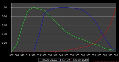
So here graphs (normalized to unity) showing in this example
1) flower (Mexican Zinnia, UV reflective flower tip): green line
2) filter (Baader U filter 2"): blue line
3) sensor (Nikon D200 mod. with quartz glass internal filter): red line

now lets add what that flower looks like after having passed the filter (pink line)

and finally what that sensor records of that (cyan line)

btw. if a normal, but UV transmitting glass lens (Noflexar 35mm - yellowish line) is used between filter and sensor, then the result looks like that:

The simple laymans terms summary: This is what the flowers reflects (green line) and what the camera records of it (cyan line) through a Baader U filter and Noflexar 35mm lens:

The bad news is, that it will only be a bit better if a quartz fluorite lens is being used, but not substantially.

So in the first case the 320-390nm Baader U filter appears like a 372BP15 bandpass filter and in the second, better example, like a 365BP16 bandpass filter. This has nothing to do with the type or quality of the Baader U filter, but is caused only by the process chain it is used within!
***THESE ARE VERY SIMPLIFIED SIMULATIONS BARE SCIENTIFIC ACCURRACY, SO NO DECISION, JUST INSIGHT SHOULD BE BASED ON THAT***
Stay tuned, more will follow on that fascinating subject...
More info on this very interesting field may be found on my site http://www.pbase.com/kds315/uv_photos
